LED lighting has transformed modern buildings, but reliable performance still depends on correct installation, ventilation, controls, and maintenance. The International Energy Agency reports that lighting uses approximately 15% of global electricity. That makes small faults financially important. The U.S. Department of Energy also states that LED products can use at least 75% less energy and last up to 25 times longer than incandescent lamps. These benefits are not automatic.
This guide, How to troubleshoot common LED lighting problems, examines flickering, unexpected dimming, buzzing, overheating, color changes, and premature failure. James R. Brodrick, a former U.S. Department of Energy solid-state lighting program manager, explained, “The LED is only one part of the lighting system.” That principle matters. A loose neutral wire, incompatible dimmer, poor driver, or trapped heat can imitate an LED defect. Check the system, not only the lamp.
Begin with observable details. Does the flicker appear during startup? Is the housing hot enough to discolor nearby plastic? Does the problem follow the bulb or remain with the socket? These simple tests often reveal the real cause. However, field diagnosis is imperfect. A multimeter reading may look normal while a driver fails under load. Manufacturer specifications can also be vague. The U.S. DOE’s Solid-State Lighting reports repeatedly stress system compatibility and thermal management. Treat those findings as practical guidance, not a guarantee. Safe isolation, qualified electrical support, and documented testing remain essential. Sometimes, the fault is not where the light disappears.
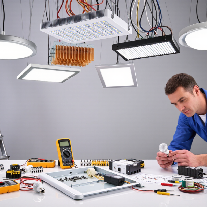
How to Troubleshoot Common LED Lighting Problems in 2026
ENERGY STAR rates many quality LED products for 25,000 to 50,000 hours. That equals roughly 17 to 34 years at four hours daily. A dark lamp after two years needs investigation, not immediate replacement.
Start with the symptom. Rapid flickering often points to a failing driver, loose wiring, or an incompatible dimmer. Slow pulsing can expose voltage instability. A lamp that glows faintly after switching off may receive leakage current from the circuit. Check the lamp in another socket, then test the dimmer’s LED compatibility. Do not ignore heat. The U.S. Department of Energy’s solid-state lighting research repeatedly identifies thermal management as a major factor in LED lifetime. A hot, enclosed fixture can shorten the expected rating.
Color changes matter too. A yellow patch, darkened lens, or uneven brightness may indicate phosphor damage or driver stress. The Illuminating Engineering Society notes that LED life is commonly measured through lumen maintenance, not sudden failure. A product can still operate while producing noticeably less light. That distinction is easy to miss. I have seen “dead” lamps recover after cooling, but that is not a repair; it is a warning. Record installation date, daily operating hours, fixture temperature, and flicker behavior. Compare those observations with the rated life and warranty documents. Report uncertainty honestly. A multimeter reading alone may not reveal intermittent driver failure.
The chart converts a 25,000–50,000-hour LED rated life into approximate years at common daily-use levels. These figures are calculated from 365 days per year and represent rated operating life, not a guarantee that an individual lamp will operate without reduced brightness, flicker, or driver failure.
Check dimmer compatibility, loose wiring, and unstable power before replacing the LED.
Thermal protection may activate when airflow is restricted or the fixture is enclosed without suitable thermal design.
Compare light output with the original specification and inspect for heat buildup, aging, or a failing LED driver.
Test the socket, switch, connections, and driver. If the fault follows the lamp, replacement is usually appropriate.
LED failures often begin with the power path, not the light engine. The IEA’s 2024 Energy Efficiency report estimates that lighting uses about 5% of global electricity. Efficient drivers deserve careful testing.
Before testing, isolate mains power and verify zero voltage with a calibrated meter. IEC 61347-1 addresses controlgear safety, including insulation, heating, electric shock protection, and abnormal operation. For LED controlgear, IEC 61347-2-13 adds requirements for electronic drivers supplied from AC or DC sources. Check the driver label, rated input, output range, polarity, and maximum load.
Restore power only when covers and protective earth connections are secure. Measure input voltage under load, then record the driver’s output voltage and current. Compare both readings with the stated limits. A high no-load voltage can damage an LED module. Excessive ripple may cause visible flicker or early component stress. Use an oscilloscope when a meter shows normal values but flicker remains.
Inspect terminals for heat discoloration. Check airflow around the enclosure. A thermal camera can reveal a loose connection before failure becomes obvious. Insulation resistance and dielectric-strength tests require suitable instruments, controlled conditions, and trained personnel. Never improvise these tests.
The U.S. Department of Energy’s 2023 Solid-State Lighting R&D Opportunities report identifies laboratory LED efficacy above 200 lumens per watt, but real installations lose performance through heat, wiring, and driver losses. I sometimes blame the LED too quickly. The driver may be the quieter failure.
How to Troubleshoot Common LED Lighting Problems in 2026
Flicker is often blamed on the lamp, but the driver, dimmer, or wiring may be responsible. Start by recording the fault. Does it appear during startup, low dimming, or camera use? A professional inspection should include a power-quality meter and a flicker measurement device. IEEE 1789 guidance links health risk to modulation depth and frequency, not brightness alone. Compare measured values with the recommended low-risk region for the tested frequency. A bright lamp can still produce uncomfortable modulation.
Dimming faults need controlled testing. Set the dimmer to 100%, 50%, and its lowest stable level. Watch for pulsing, buzzing, sudden shutdown, or uneven light between fixtures. Check neutral connections, load compatibility, and the driver’s dimming method. Never assume a replacement control will solve the issue. Some measurements can mislead when the meter samples too slowly. I have seen “stable” readings change after the fixture warmed for ten minutes.
Tips: Use a slow-motion phone video as an initial clue, not proof. Test one fixture against another under identical settings. Record frequency, modulation percentage, ambient temperature, and dimmer position. If flicker remains, disconnect the control circuit only through a qualified electrician. Human comfort varies, and IEEE 1789 is guidance rather than a complete diagnostic procedure. Recheck the installation after repairs. Small wiring errors matter.
| Observed Symptom | Likely Fault Area | Recommended Measurement | Practical Diagnostic Threshold or Reference | Corrective Action | IEEE 1789 Relevance |
|---|---|---|---|---|---|
| Visible flicker at normal viewing distance | Excessive low-frequency ripple in the driver output | Use a calibrated photodiode or flicker meter; record modulation frequency, percent flicker, and flicker index | Check for modulation at twice the mains frequency: typically 100 Hz on 50 Hz systems or 120 Hz on 60 Hz systems. IEEE 1789 evaluates risk using modulation depth and frequency together. | Replace or repair the driver, improve DC filtering, and verify the replacement at the intended dimming level | Compare measured modulation with the IEEE 1789 recommended practice curves; do not rely on a single universal percentage limit |
| Flicker appears only when dimmed below approximately 20% | Minimum-load limitation, unstable constant-current regulation, or unsuitable dimmer compatibility | Measure LED current and optical output while stepping through 100%, 50%, 20%, 10%, and minimum dimming levels | A sudden increase in modulation, intermittent output, or irregular duty-cycle pulses at low settings indicates a control-loop or compatibility problem | Use a compatible dimmer-driver combination, set the minimum level above the unstable region, or select a driver designed for low-end dimming | Assess the complete dimming range, because modulation can change substantially as the commanded light level decreases |
| Light output drops out or flashes during phase-cut dimming | Insufficient holding current, excessive inrush, leading-edge/trailing-edge mismatch, or minimum-load incompatibility | Check dimmer type, load current, startup behavior, and the AC waveform with suitable electrical test equipment | If the lamp works at full output but drops out at intermediate settings, suspect control compatibility rather than LED thermal failure | Verify the dimmer's rated LED load range and use the control method specified for the driver | After resolving dropout, repeat optical measurements because unstable conduction can create high low-frequency modulation |
| Camera banding or rolling bars; no obvious flicker to the eye | Interaction between light modulation and camera shutter or frame timing | Test with the actual camera, shutter speeds, frame rates, and exposure settings used in the application | Visible banding may occur even when ordinary visual inspection shows no problem; test at common rates such as 24, 25, 30, 50, and 60 frames per second | Use a low-modulation driver, increase the modulation frequency where appropriate, or synchronize lighting and camera settings | IEEE 1789 addresses temporal light modulation and potential biological effects; camera compatibility requires an additional application-specific test |
| Flicker begins after the luminaire warms up | Driver thermal stress, capacitor aging, inadequate heat dissipation, or a temperature-sensitive control circuit | Measure optical modulation and LED current at startup and after thermal stabilization; inspect driver temperature and ventilation | A fault that appears only after warm-up is consistent with temperature-dependent component or protection behavior | Improve thermal management, correct enclosure ventilation, or replace the degraded driver | Record IEEE 1789-related measurements at the actual operating temperature, not only in a cold-start condition |
| Random flashing across multiple fixtures | Loose wiring, unstable supply voltage, control-bus interference, or incompatible control devices | Check line voltage, neutral integrity, control wiring, grounding, and event timing across several fixtures | If several fixtures change simultaneously, investigate the shared supply or control network before replacing individual LED modules | Tighten and correctly terminate wiring, correct supply disturbances, separate incompatible control signals, and retest under load | Evaluate the resulting optical waveform after electrical stability is restored |
| Uneven brightness between fixtures on the same control setting | Driver current tolerance, control-signal scaling error, wiring voltage drop, or different minimum-output settings | Measure control signal, input voltage, LED current, and optical output at identical commands | Compare fixtures at 100%, 50%, and low-level output; a mismatch that grows at low levels often indicates dimming-range differences | Standardize driver settings, correct voltage drop, calibrate the control system, or replace out-of-tolerance drivers | Measure each operating point because flicker percentage and flicker index are not necessarily constant across the dimming range |
| Stroboscopic effects on moving objects or rotating equipment | Periodic light modulation interacting with the object's speed or motion frequency | Use a flicker meter capable of reporting frequency and modulation; observe moving machinery only under safe conditions | Risk depends on modulation amplitude, frequency, viewing conditions, and motion; a higher frequency alone does not guarantee acceptable performance | Reduce modulation, select a suitable driver, and verify the installation at the relevant machine speeds | Use the IEEE 1789 recommended and no-effect-level curves as design references, then perform an application-specific motion assessment |
| Dimming command changes but light level does not respond smoothly | Incorrect 0–10 V polarity or range, PWM signal mismatch, digital-addressing error, or driver configuration fault | Measure the control signal under minimum, midpoint, and maximum commands; compare the waveform and polarity with the control specification | A discontinuity, dead zone, or unexpected reset in the control signal can produce abrupt current changes and visible modulation | Correct wiring and configuration, match signal type and range, and update or replace incompatible control hardware | Confirm that the optical output remains within the selected IEEE 1789 risk guidance throughout the command range |
| Persistent low-level glow when switched off | Leakage current through an illuminated switch, indicator circuit, parallel wiring, or electronic switching device | Verify isolation with power safely controlled and inspect switching topology; do not bypass protective devices | A small leakage current can charge the input circuit enough to produce intermittent glow or periodic flashes | Use a compatible switch, add an approved bypass component where permitted, or revise the switching arrangement | After the off-state issue is corrected, verify that no residual periodic modulation remains during normal operation |
When an LED fixture dims or changes color, measure before replacing parts. Excess heat often shortens lumen life and accelerates chromaticity shift. Check the heat sink, mounting surface, airflow, and driver current. Record the LED case temperature after the fixture reaches thermal stability. A warm housing is not automatically a failure. The measured value must match the product’s rated conditions.
LM-80 provides laboratory data for lumen maintenance and color stability in LED packages or modules. Tests commonly run at controlled temperatures and drive currents for thousands of hours. TM-21 uses LM-80 results to project long-term lumen maintenance. It is a calculation, not a direct prediction of every installed fixture. Compare the test conditions with the real environment. A projection based on mismatched temperature or current can mislead a technician. This limitation deserves more attention.
Photograph the installation before testing. Note ambient temperature, operating hours, dimming level, and visible color differences. Use calibrated instruments when checking illuminance and chromaticity. Look for changes in the u′v′ coordinates, not only obvious yellowing. Inspect several fixtures, including one near a ceiling and another in open air. Small samples can hide a pattern. Recheck after cleaning vents or correcting thermal contact. Do not treat one unusual reading as final evidence. Sometimes the first diagnosis is simply wrong.
How to Troubleshoot Common LED Lighting Problems in 2026
Start with measured lumens, not wattage. A 10-watt lamp may consume little power but still deliver poor light. The U.S. Department of Energy’s LED Lighting Facts database lists tested lumens, wattage, and efficacy for individual products. For many complete LED luminaires, 80–150 lm/W remains a practical comparison range. DOE’s 2024 Solid-State Lighting R&D Opportunities report also separates laboratory package performance from real fixture performance. Laboratory devices can exceed 200 lm/W, but lenses, drivers, heat, and housings reduce delivered output.
Measure the light at the work surface with a calibrated lux meter. Then compare the result with the manufacturer’s rated lumens and DOE-listed efficacy. A dirty diffuser can cut visible output noticeably. Excess heat may also reduce brightness and shorten useful life. I have seen fixtures rated at 120 lm/W perform closer to 90 lm/W after installation. That difference is not always a defect. Sometimes, the room surface absorbs more light than expected. Still, a sudden drop suggests loose wiring, dimmer incompatibility, or driver failure.
Tips: Record lumens, watts, color temperature, and operating hours. Check output after thirty minutes, not immediately. Compare identical fixtures under identical conditions. Treat 80–150 lm/W as a guide, not proof of quality. DOE data is useful, but field measurements remain imperfect.
Isolate mains power and verify zero voltage with a calibrated meter. Check input ratings, output range, polarity, and maximum load. Restore power only after covers and protective earth connections are secure.
Measure input voltage while the driver is operating under load. Record output voltage and current. Compare both readings with the stated limits. A high no-load voltage may damage the LED module.
Check for visible flicker, excessive ripple, heat discoloration, and poor airflow. Use an oscilloscope when a meter appears normal but flicker continues. A thermal camera may reveal a loose terminal before failure becomes obvious.
No. These tests require suitable instruments, controlled conditions, and trained personnel. Never improvise them. Serious injury or equipment damage can result.
Let the fixture reach thermal stability, then measure the LED case temperature. Inspect the heat sink, mounting surface, airflow, and driver current. A warm housing is not automatically defective. The rated conditions matter.
LM-80 provides laboratory data for lumen maintenance and color stability. TM-21 projects long-term maintenance from that data. It is a calculation, not a guarantee for every installed fixture. Conditions may not match reality.
Measure illuminance at the work surface with a calibrated lux meter. Record lumens, watts, color temperature, and operating hours. Many complete fixtures fall near 80–150 lm/W, but this is only a comparison guide.
Heat, wiring, drivers, lenses, housings, and dirty diffusers can reduce delivered output. Measure after about thirty minutes, not immediately. Compare identical fixtures in similar locations. My first diagnosis may still be wrong.
How to troubleshoot common LED lighting problems starts with identifying the symptoms: premature failure, reduced brightness, uneven illumination, flickering, or unexpected color changes. Compare the expected service life with the typical 25,000–50,000-hour LED rating, then inspect connections, power supplies, and drivers. Testing should be performed carefully while considering IEC 61347 safety requirements, especially when checking voltage stability, overheating, or component failure.
For flicker and dimming issues, isolate the fixture, control system, and dimmer, using IEEE 1789 guidance to evaluate potential risks from modulation. Heat-related problems can be assessed by examining ventilation, operating temperature, and color shift through LM-80 and TM-21 methods. Finally, compare measured light output with DOE data and practical efficiency benchmarks of approximately 80–150 lumens per watt. This structured process helps distinguish electrical faults, thermal stress, control incompatibility, and normal performance decline.

Senning Lights